Category: Technical Guides

Tooling, tolerance and application guidance for CNC knife cutting.

  • Oscillating Knife Tooling Guide: Blades, Rotary and Pneumatic Knives

    Oscillating Knife Tooling Guide: Blades, Rotary and Pneumatic Knives

    The tool is the part of a CNC cutting machine that touches the product. A perfectly rigid frame cannot compensate for the wrong blade, a dull edge or a tool that is incompatible with the material.

    This guide explains the main tool families and the questions that decide the selection.

    Oscillating knife

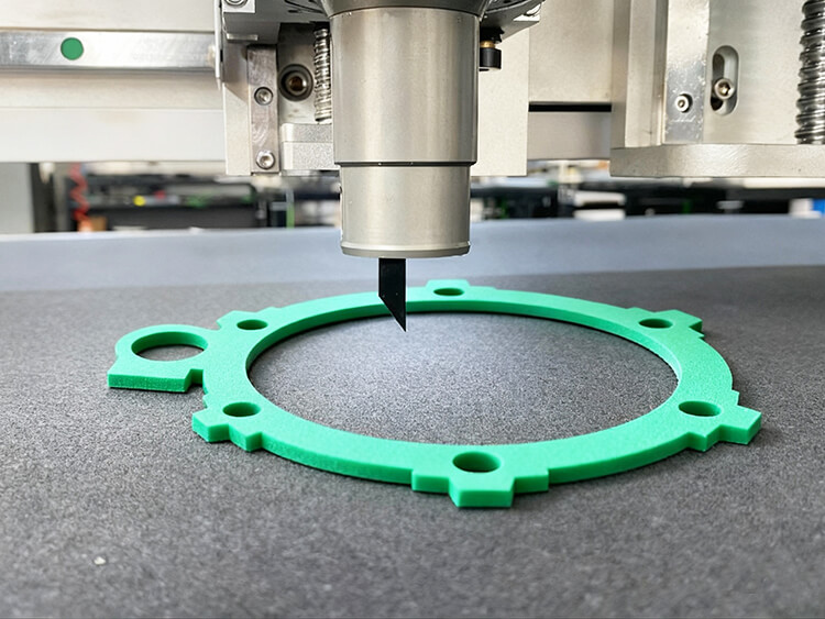
    An oscillating knife moves a blade rapidly up and down while the head follows the cut path. It is the most common tool for flexible and fibrous materials.

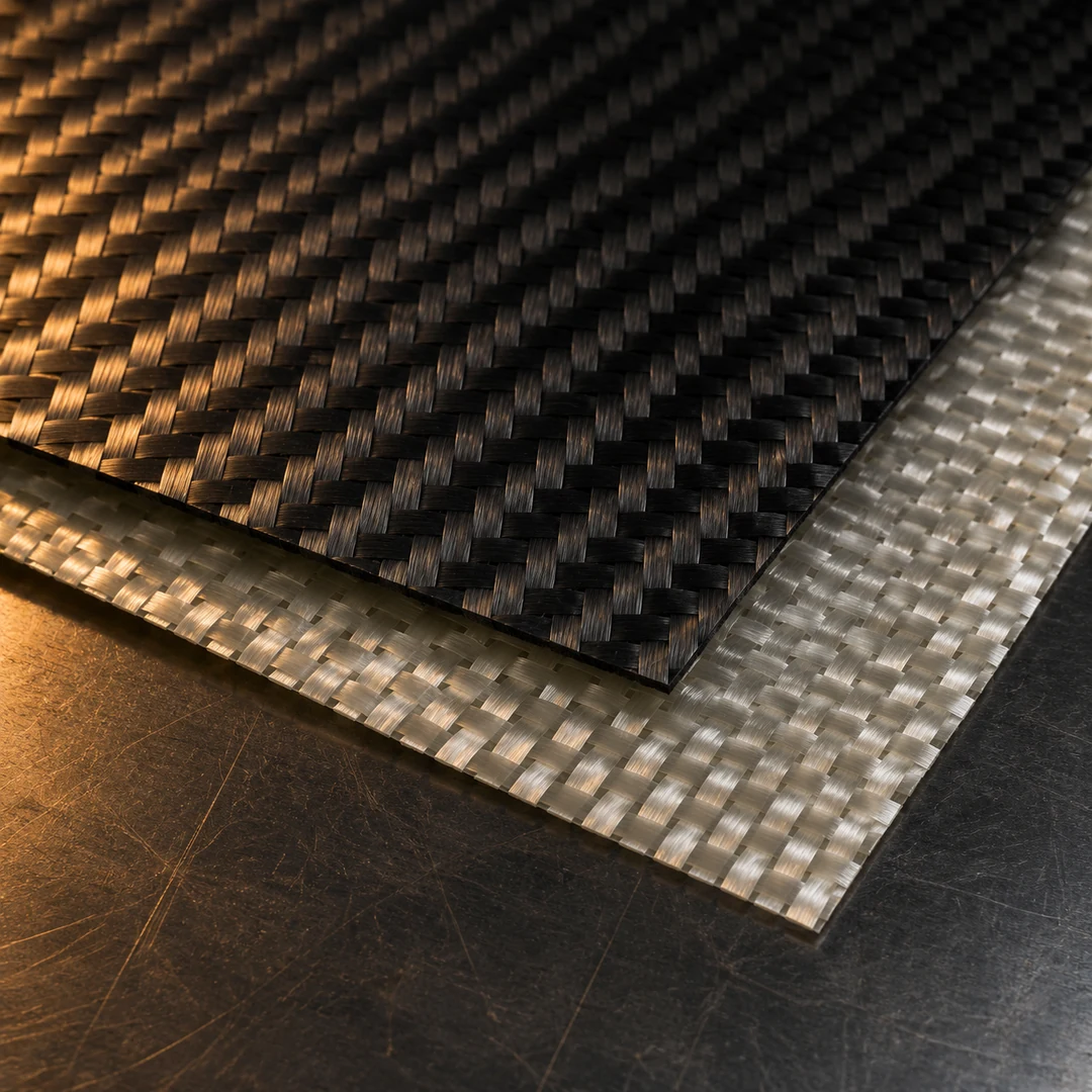
    Use it for: gasket sheet, foam, leather, felt, fabric, cardboard, composite fabric and many insulation materials.

    Watch for: blade wear, material deflection, hold-down, speed and the correct blade angle. A worn blade can tear rather than cut.

    Rotary knife

    A rotary knife uses a circular blade that rotates as it moves through the material. It can be effective on dense or thick materials and some textiles.

    Use it for: selected technical textiles, carpet, leather and composite materials where a rotating edge suits the construction.

    Watch for: heat and wear at the edge, blade alignment and material pull. The tool is not universal.

    Drag knife

    A drag knife follows the direction of travel with a passive, angled blade. It is common for vinyl, film, labels and thin materials.

    Use it for: kiss-cutting, printed vinyl, film and thin sheet.

    Watch for: corner geometry and blade orientation. A drag knife can struggle with thick or highly resistant materials.

    Pneumatic knife

    A pneumatic knife uses air pressure to drive a reciprocating blade. It can suit softer foam and materials that need a different cutting action from a standard oscillating head.

    Use it for: EPE, sponge and selected soft foams.

    Watch for: air supply, maintenance and the correct blade for density.

    Milling tool

    A milling tool removes material with a rotating cutter. It is not a knife, but it is often combined with one on foam and packaging machines.

    Use it for: internal cavities in EVA, EPE and similar foam inserts, and selected rigid materials.

    Watch for: chip extraction, dust, tool wear and the need to hold the part securely.

    Creasing and V-groove tools

    A creasing wheel compresses a fold line without cutting through. A V-groove tool removes a V-shaped channel for a clean fold on thicker board.

    Use them for: corrugated packaging, gift boxes, displays and duct board.

    Watch for: board thickness, groove angle, fold direction and the condition of the creasing wheel.

    Punch and marker tools

    A punch makes a clean hole; a marker/plotter tool draws a reference line or part number.

    Use them for: acoustic panels, leather, packaging and composite ply kits.

    Watch for: punch size, material density, marking ink compatibility and tool clearance.

    How to choose the blade

    Ask these questions:

    1. What is the material and binder?
    2. What is the thickness range?
    3. Is the material abrasive or soft?
    4. Is the edge visible or hidden in the assembly?
    5. Does the material fray or melt?
    6. Does it need a sealed edge?
    7. Is the part single-layer or stacked?
    8. How many metres or parts per shift?
    9. What is the blade-change interval?
    10. What is the cost per good part?

    A blade that lasts longer may produce a worse edge. A blade that produces a beautiful sample may wear too quickly in production. The test should compare quality and life.

    Tool-change discipline

    A cutting file may require several tools. The machine should have a clear tool-change sequence, a reference position and a way to verify that the correct tool is installed.

    Operator controls should include:

    • tool number and name
    • blade type and condition
    • depth setting
    • speed and oscillation
    • number of passes
    • material recipe
    • maintenance or replacement trigger

    A practical test sheet

    For each material, record:

    FieldExample
    Material1.5 mm graphite laminate
    ToolOscillating knife, 0.6 mm blade
    Feed600 mm/s
    Oscillation3000 strokes/min
    VacuumZones 1–3
    Passes1
    Edge resultClean, no delamination
    Blade life7–10 days under test conditions

    Use the record as the starting recipe, then refine it in production. Do not let a generic tool list become the actual process.

    Start with a cutting test or explore the relevant material page such as gasket cutting or composite cutting.
  • CNC Cutting Tolerance: What ±0.1 mm Really Means

    CNC Cutting Tolerance: What ±0.1 mm Really Means

    “±0.1 mm” appears in many CNC cutting machine brochures. It is a useful number, but it is not a complete answer. The tolerance of a finished part depends on the machine, the material, the tool and the way the material is held.

    The buyer needs to separate machine positioning accuracy, repeatability and part tolerance.

    Machine accuracy

    Machine accuracy describes how closely the cutting head reaches the commanded position under defined conditions. It is influenced by the frame, guide rails, rack, servo system, calibration and compensation.

    Repeatability

    Repeatability describes how closely the machine returns to the same position over repeated cycles. A machine can be reasonably accurate but inconsistent, or precise but offset by a constant amount.

    Part tolerance

    Part tolerance is the result the customer measures on the finished part. It includes:

    • machine accuracy
    • material movement
    • knife deflection
    • blade wear
    • vacuum hold-down
    • table surface condition
    • cutting speed
    • number of passes
    • nesting and tool-path direction
    • measurement method

    A thin, stable gasket sheet may approach the published machine tolerance. A thick foam block or a soft felt panel can move more, so the practical part tolerance may be wider.

    Why ±0.1 mm is not a promise for every material

    The same machine can produce different results across materials. A dense, thin sheet may be held firmly and cut cleanly. A compressible foam can deflect under the blade and recover differently. A woven fabric can pull or fray.

    The test condition matters. Ask:

    • What material was cut?
    • What thickness?
    • Which knife and angle?
    • What vacuum and table surface?
    • What feed and oscillation?
    • What was measured, and with what instrument?
    • Was the measurement taken on the first part or across a production run?

    A responsible supplier should provide this context, or at least confirm the test on your material.

    How to improve the result

    Match the knife and blade

    The wrong blade can push the material instead of cutting it. A sharper or thinner blade may improve a soft material; a stronger blade may be needed for dense sheet.

    Use the right hold-down

    Zoned vacuum, a suitable sacrificial mat and correct loading help stabilise the material. Small parts may need a different zone strategy or a support material.

    Control the speed

    Higher speed is not always better. A slower feed can improve edge quality and dimensional stability in difficult material.

    Use more than one pass

    A controlled multi-pass cut can reduce deflection in thick or dense material. The right number of passes is determined by the test.

    Maintain the table

    A worn or contaminated mat changes hold-down and cut depth. Replace wear surfaces on a defined schedule.

    Measure correctly

    Use a calibrated instrument and a defined measurement method. Compare the same feature across parts. Record the result.

    What to put in the RFQ

    Instead of asking only for “±0.1 mm”, specify:

    • critical dimensions and tolerance
    • material and thickness
    • part size
    • cutting method allowed
    • inspection method
    • acceptable edge quality
    • production rate
    • whether the tolerance applies to the first article or every part

    Then require a sample report that connects the test parameters to the measured result.

    When to challenge a claim

    Ask for evidence when a supplier:

    • promises the same tolerance for every material
    • cannot explain the test conditions
    • measures a machine axis but not a finished part
    • ignores vacuum, knife wear or material movement
    • refuses a sample test

    The right tolerance is the one the process can repeat on your material at the required output.

    Request a cutting test and review the machine range before fixing the specification.

Chat on WhatsApp